SOFTWARE
In our previous blog, we introduced common CAD-related “myths,” explored typical geometric issues, and highlighted the importance of geometry cleanup along with its advantages. We also outlined a CAE analyst’s workflow for debugging such issues and discussed modeling strategies using an aircraft example.
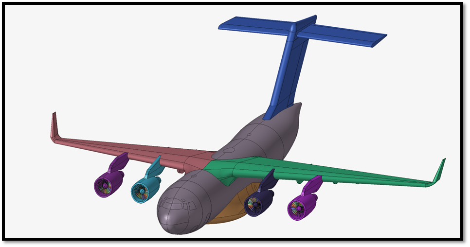
Building on that foundation, engineers at Designfusion will now use the cleaned aircraft geometry prepared in Simcenter HyperMesh 2026 to perform advanced simulations in Simcenter OptiStruct.
Any structure that we evaluate must be mathematically stable; that is, the applied constraints must sufficiently resist all translations and rotations. This stability is commonly observed in structures that are fixed to the ground or bolted to other structures.
Have you ever considered how we evaluate structures that move through the air, like an aircraft, or those freely floating in outer space, like a satellite?
In these cases, external forces such as aerodynamic loads (arising from pressure differences), thrust, and self-weight act on the structure. However, since these systems are not physically constrained, conventional static analysis leads to instability due to unconstrained rigid body motion. For systems like these, when we analyze deflections and the stress on the body due to applied mechanical forces, they must satisfy the equilibrium condition. Since the systems are flying or floating in the air and space, we cannot constrain them to maintain their attitudes; thus, the equation becomes unstable.
To address this, engineers at Designfusion adapted a special form of Linear Static analysis called “Inertia Relief Analysis”. This analysis allows the simulation of unconstrained or partially constrained structures. It calculates the stress and deformations that we expect in a steady-state, mathematically stable simulation.
In “Inertia Relief Analysis”, the applied mechanical forces are balanced by rigid body accelerations and forces. These accelerations and forces are distributed over the structure in such a way that the total of the applied forces on the structure is zero, achieving equilibrium.

Referring to the aircraft model from the previous blog, we will demonstrate the setup and results of this inertia relief analysis.
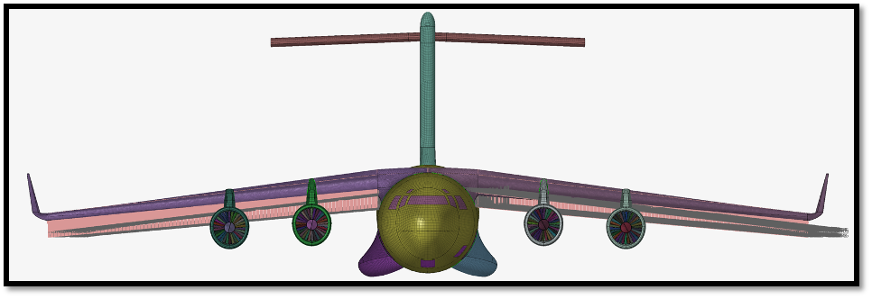
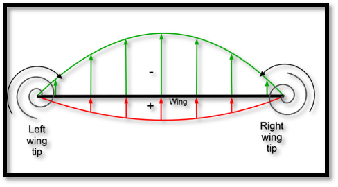
We meshed the model with 1D, 2D, and 3D elements to represent the geometry and capture features. Material data was used from ASM Aerospace Specification Metals Inc. The 2.04G pull-up force was applied in an elliptical form to represent the forces. The major contribution of the force is close to the root of the wing in the form of an elliptical force, as shown below.
Note: The scale of the displacement contour in images 5 and 6 is enhanced for better visualization.
Equilibrium can be evaluated in another way.
A force of 2.04G is applied along the Z axis, and the resulting rigid body forces are computed with respect to the model’s center of gravity. The corresponding moments of the X and Y axes are also calculated.
To compute rigid body accelerations, we need to extract the rigid body mass matrix at the center of the gravity position. So, we have forces and moments acting at the center of gravity and the rigid body mass matrix at the center of gravity.
Using the formula F=Mass*Acceleration , and by performing rigid body mass matrix inversion, we can determine the rigid body accelerations.
Below is an image of the rigid body acceleration and forces that were calculated using Simcenter Optistruct.
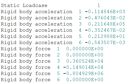
If the system must be in equilibrium, the difference between the external force and the product of mass and rigid body accelerations should be zero.
F_(applied mechanical force)-{M_(mass matrix at center of gravity)*A_(rigid body accelerations) }=0
Certified engineers at Designfusion can perform such complex simulations for companies in the aerospace and mechanical industries. Along with advanced simulations, we can help organizations with their design optimization and 3D printing needs.
We are here to help – feel free to reach out anytime.

Lohith Porwal is an Application Specialist and has over 7 years of experience as a CAE analyst. He has been with Designfusion since October 2024, supporting Siemens CAE tools. His main focus is developing workflows and providing support on live projects.
Designfusion is the largest dedicated solution provider of Siemens PLM software in North America. With an expert support team and a decade of history in the industry designfusion is the #1 choice for companies looking to best enhance their software acquisition.
305 Milner Ave, Suite 308,
Toronto, Ontario, M1B 3V4
Canada
Phone: 416 267-5542
Toll Free: 1-888-567-3933
2734, rue Étienne Lenoir Laval, Quebec. H7R 0A3
Canada
Phone: 514-761-5682
Toll Free: 1-866-534-5682
565, rue Shefford, Suite 1
Bromont, Québec, J2L 1C2
Canada
Phone: 450-534-5682
Toll Free: 1-866-534-5682
1400 E Touhy Ave, Suite 477
Des Plaines, IL 60018
USA
Phone: 847-439-0555
Toll Free: 1-866-921-1830
2900 Auburn Court
Auburn Hills, MI 48326
USA
Toll Free: 1-866-921-1830
151 Castleberry Ct. Ste.
CMilford, OH 45150
USA
Toll Free: 1-866-921-1830
60 Scarsdale Rd, Unit 119
Toronto, Ontario, M3B 2R7
Canada
1919, Boulevard Lionel-Bertrand Suite 101, Boisbriand,
QC J7H 1N8, Canada


